ME312 Assignment: Hydraulic System Design for Manufacturing Process
| University | Angela's Collage (AC) |
| Subject | ME312 Hydraulic System Design |
Design Brief
A hydraulic system is to be designed to conduct several stages of a manufacturing process, namely:
• Stage I: Move a component from location A to location B along a rotating
conveyer belt, ensuring adequate control of the speed of the conveyor belt.
• Stage II: When the component arrives at position B, the component will roll onto
a table. The table will then be lifted a distance at a set speed once the hydraulic
motor has come to a complete stop. The design should ensure that the table
does not tilt, even if the component is located to one side of the lift table.
• Stage III: Once the component reaches the maximum extension of the lift table,
two actuators are then utilised to apply different forces to the component, as
detailed in the individual specifications. These loads must be applied for a fixed
amount of time.
• Stage IV: Once the time has been exceeded, the lift is finally lowered to its
original position, and the component is manually removed by an employee, with
the system operating in a low-pressure setting.
The system must include high-pressure and low-pressure operation modes.
The lowpressure operation mode is a standard configuration for all system parameters (i.e.
this part of the system just needs to be included in the circuit diagram but assume a
system pressure requirement of 60 psi and maximum flow-rate of 7.0 l∙min-1
for the low pressure pump).
The hydraulic system is to be operated using two electric motors
(high-pressure and low-pressure system) connected to the grid via a 3-phase
transformer, with both the electric motors and 3-phase transformer to be specified as
part of the design (i.e. selection of a 3-phase transformer using the standard sizes
supplied by ESB Networks and the electric motors must be selected from Baldor only).
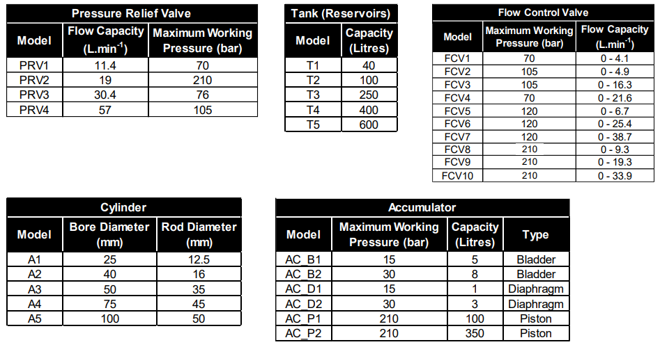
A library of key components is presented in Appendix A. For components not listed in
this Appendix (e.g. the low-pressure pump, flow dividers or pressure control valves
other than pressure relief valves) which may be required to support your design, these
components can be added in as generic components in the system and given a clear
part number in your Parts List. However, for components listed, you must use these
components to design your system and adjust system pressure or flowrate in the
system as necessary to meet the design requirements and critical values such as
cracking pressures must be clearly specified for each of these additional components
in your design report.
Are You Searching Answer of this Question? Request Ireland Writers to Write a plagiarism Free Copy for You.
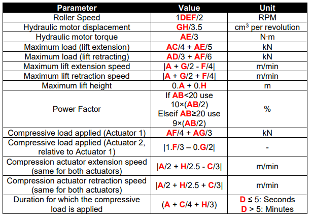
The following system specific parameters are based on your student ID. Your student
ID is of the form:
ABCDEFGH

Report
The report should include the following sections:
• Design Brief
• Design Specification
• Circuit Diagrams
• Parts List
• Overview and Justification of Part Selection Design Brief: Overview of the problem as presented.
Design Specification: Based on the brief provided, the key design requirements and
constraints should be identified and listed (bullet points will suffice).
Circuit Diagram: A full circuit diagram of the hydraulic system should be provided
using standard hydraulic symbols. Part numbers should be included as well as clear
definition of the working lines.
Parts List: The parts list should refer to the part identification number in the circuit
diagram and to the part number as per the manufacturer’s description (e.g. as per the
part name on the list of attached components). The electric motor should be specified
from Baldor (www.baldor.com).
Overview and Justification of Part Selection: The selection of each component
should be described and justified (including any theory required in the selection
process). For example: “A pump isolation check valve inserted downstream of the hydraulic pump to …. . The
cracking pressure of this check valve is set at … bar.”
“The torque required at the outlet of the electric motor is:
𝑇 = √3𝑉𝐼𝜂motor cos 𝛼 𝜔
(1)
where 𝑉 is voltage, … .”
Note the layout of the equations needs to follow standard engineering convention.
Marking Scheme
The breakdown of marks for this assignment are:
• Design Brief (5 Marks)
• Design Specification (10 Marks)
• Circuit Diagram (30 Marks)
• Parts List (10 Marks)
• Overview and Justification of Part Selection (30 Marks)
• Report Structure (15 Marks)
Get Solution of this Assessment. Hire Experts to solve this assignment for you Before Deadline.
Appendix A: List of Available Components


If you are struggling with ME312 Hydraulic System Design Assignment? Unable to meet your deadline? And you want someone to do my assignment. You are in the right place. Our platform provides the Best Ireland Assignment Helpers, who are knowledgeable and skilled writers who can give you high-quality, plagiarism-free solutions and assignments with original content. Contact us now; your assignment will be completed on time. That will help you get high grades. We also provide free sample assignments to help you.
