An mbed (LPC1768) is Connected to a Laptop using a USB Cable: Instrumentation, Monitoring & Control Assignment, ITT
Q1.
An mbed (LPC1768) is connected to a laptop using a USB cable. The mbed uses the Serial class to communicate with the laptop. The following program demonstrates how the mbed can both transmit to the laptop and receive from the laptop:
#include “mbed.h”
Serial pc(USBTX, USBRX); // tx, rx
int main() {
pc.printf(“Hello World!\n”);
while(1) {
while (!pc.readable()); //wait to receive
char x=pc.getc(); //read a char from the laptop
while (!pc.writeable()); //wait for mbed to be able to
//communicate
pc.printf(“You hit: %c”,x); //echo back
}
}
The communication between the laptop and the mbed occurs as follows:

Write a Mbed C function to implement the communication as outlined above. You only have to write the Mbed code. You may assume that ACK and NAK are #defined. The declaration AnalogIn ain(p20); has already been declared.
Additional Information:
The analog samples are read using ain.read_u16(). As the value read is a 16-bit number, it must be transmitted as two separate 8-bit numbers, low byte first, then high byte. The 200 samples must be added together during the transmission. After the 200 samples have been transmitted, transmit the checksum as a 16-bit number (low byte followed by high byte). Wait for the laptop response and return a value as indicated above.
Q2.
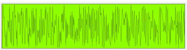
Consider the following C# function, this function is invoked on a click to the drwBtn object. The function draws random lines in a rectangle. The rectangle is sized according to the form width and height. Thus, this rectangle will fit any screen resolution.
private void drwBtn_Click(object sender, EventArgs e)
{
this.WindowState = FormWindowState.Maximized; //maximise the form
int maxx = this.Width;
int maxy = this.Height;
int x1 = maxx/20, y1 = maxy / 2; //coordinates for the rectangle.
int xwidth = maxx – 2 * x1; //the rectangle is xwidth in width
int ywidth = maxy – maxy/10 – y1;// rectangle is ywidth in height
int[] vals = new int[xwidth]; //array for the data
Random rnd = new Random(); //random number generator
for (int i = 0; i < xwidth; i++)
{
vals[i] = rnd.Next(0, 65535); // fill array with random 16 bit data
}
System.Drawing.Graphics myGraphics; //graphics stuff
myGraphics = this.CreateGraphics();
Pen myPen = new Pen(System.Drawing.Color.Black, 4);
SolidBrush yellBrush = new SolidBrush(Color.GreenYellow);
myGraphics.DrawRectangle(myPen, x1, y1, xwidth, ywidth); //draw rectangle
myGraphics.FillRectangle(yellBrush, x1, y1, xwidth, ywidth); //fill the rectangle
Pen linePen = new Pen(System.Drawing.Color.Black, 1);
//black line will be used 1 pixel wide
int oldx, oldy, newx, newy; //4 points for a line
oldx = x1; //very first x point
oldy = y1 + ywidth ; //very first y point
double ymod = (ywidth – 10) / 65535.0; // convert the range of values 0..65535 into
// a range of y values (approx 0 .. 750) this is the y scale
int mod = 4; //number of x pixels to skip for every line
for (int i = 0; i < (xwidth/mod); i++) //draw the lines
{
newx = oldx + mod; // in the line, this is the x2 value
double yval = (double)vals[i]; //cast the random data to double
yval *= ymod; // scale it to pixels
newy = y1 + ywidth – 5 – (int)yval; // make it fit to screen as the screen origin is
//top left hand corner, the 5 makes sure our line never touches the boundary of rectangle
myGraphics.DrawLine(linePen, oldx, oldy, newx, newy);
oldx = newx; //the next line must begin where the old line ends
oldy = newy;
}
The output of this code is as follows:
Consider the following C# code:
private void ReadSamples(void)
{
for (int i = 0; i < 100; i++)
{
int x,y ;
while (pcPort.BytesToRead == 0); //wait for low byte
x = pcPort.ReadByte(); //read low byte
while (pcPort.BytesToRead == 0); //wait for high byte
y = pcPort.ReadByte(); //read high byte
vals[i] = (x + (y << 8)); //make a 16 bit sample, store in a global array.
}
}
This function reads 100 ADC samples from the serial port. Each sample is 16 bits, so, each sample is composed of two serial port reads. In the above example, x is the low byte, y is the high byte. The code also shows how the low byte, high byte values are recombined to a 16-bit value and then stored in a global array of type int (vals).
Using the two functions given, write a C# function that sets the form to maximized state, then reads 200 Analogue samples (16 bits) from the serial port. Obviously, these samples can vary from 0 to 65535. As the samples are being received, plot them graphically in a rectangle 800 pixels wide (x-axis), 500 pixels high (y-axis).
The rectangle location is as follows:
Top left: (100,300). Top right: (899,300). Bottom left: (100,799). Bottom right: (899,799). Assume for your rectangle that the bottom left coordinate is the origin of the plot. The sample received is to be plotted on the y-axis, you may assume that a sample of 0 (0x0000) will be plotted in y position 799. A sample of 65535 (0xFFFFF) is to be plotted in y position 300. The x-axis coordinate for each received sample is calculated so as to ensure that the last sample received (the 200th) will have an x-axis coordinate of 899. The sample values are to be plotted as a series of joined lines.
NB: This function is not intended to fit every screen resolution. There is NO NEED to make the rectangle plot dependent on a screen setting. Just set it to the values given.
Stuck in Completing this Assignment and feeling stressed ? Take our Private Writing Services
Q3.
(a) In the following circuit, Find Vout:

(b) In the following circuit, calculate V1, V2, and V3.

(c) In the circuit of part (b), calculate the value R4 should be set so as to balance the bridge.
(d) Explain why a differential signal is preferable to a single-ended signal when connecting a sensor to an amplifier.
(e) An instrumentation amplifier has a differential gain of 250 and a CMRR of 85 dB. A signal from a Wheatstone bridge has a value of 6.75mV and during transmission to the Instrumentation Amplifier picks up 1V of noise. Calculate the output voltage of the amplifier.
Q4.
(a) The following circuit shows a Wheatstone bridge arrangement of 4 strain gauges which are bonded to a metal specimen, with two gauges in compression and two in tension. The gauges all have the same ∆𝑅𝑅 (all are subjected to the same strain). The unstrained resistance of the gauges is 110 Ω. The gauge factor for all four gauges is 2.1. Young’s modulus for the metal is 270GN/m2, calculate the stress each gauge is subjected to.
For a strain gauge, ∆𝑅/𝑅 = 𝐾𝐾 ∈.
The gain resistor of the AD620 is given by 𝑅𝑅𝑅𝑅 = 49400/𝐺𝐺−1, where G is the gain.

(b) Consider the following op-amp circuit with negative feedback. Show that the gain of the circuit G = Vout/Vin B ≈ 1

Explain the significance of this value for the circuit gain.
(c) A load cell is used to measure loads in the range 0Kg to 10,000Kg. If an ADC with n bits are used to quantize this load range, fill in the following table.

Q5.
(a) A platinum resistor which has a resistance of 110 Ω at 0˚C is connected into a Wheatstone bridge as follows:
For the indicated differential voltage, calculate the temperature being measured given that: the coefficient of resistance of Platinum is 3.9.10-3, also Rt = R0 ( 1 + αt )
(b) For the following circuit, calculate V1.

(c) The circuit from part (a) is connected to a differential amplifier as follows:

Calculate the new value of V1, thus explain why the instrumentation amplifier is greatly preferred to the differential amplifier.
(d) For the following circuit, given Vo=(Vb-Va), show that Vo = (V1-V2)( 1 +2R/Rx).

We offer high-quality Instrumentation, Monitoring & Control assignment help to ITT students in Ireland who are stuck with these types of assignment writing tasks. Our assignment experts are available 24/ to provide you online live chat support and resolve your queries instantly.