CSAD402 -DC Motor System Assignment | MATLAB Solutions & Assessment Help
| University | University of Michigan (UOM) |
| Subject | CSAD402 Assignment: DC Motor System Modelling |
Physical setup
A common actuator in control systems is the DC motor. It directly provides rotary motion and, coupled with wheels or drums and cables, can provide translational motion. The electric equivalent circuit of the armature and the free-body diagram of the rotor are shown in the following figure.
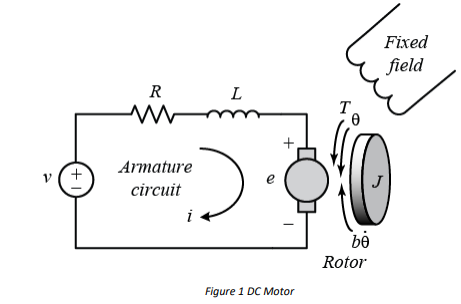
Figure 1 DC Motor
For this example, we will assume that the input of the system is the voltage source ( ) applied to the motor’s armature, while the output is the rotational speed of the shaft. The rotor and shaft are assumed to be rigid. We further assume a viscous friction model, that is, the friction torque is proportional to shaft angular velocity.
The physical parameters for our example are:
(J) moment of inertia of the rotor Value assigned to each student kg.m^2
(b) motor viscous friction constant 0.1 N.m.s
(Ke) electromotive force constant 0.01 V/rad/sec
(Kt) motor torque constant 0.01 N.m/Amp
(R) electric resistance 1 Ohm
(L) electric inductance 0.5 H
Are You Searching Answer of this Question? Request Ireland Writers to Write a plagiarism Free Copy for You.
System equations
In general, the torque generated by a DC motor is proportional to the armature current and the strength of the magnetic field. In this example we will assume that the magnetic field is constant and, therefore, that the motor torque is proportional to only the armature current by a constant factor as shown in the equation below. This is referred to as an armature-controlled motor.
![]()
The back emf is proportional to the angular velocity of the shaft by a constant factor.
![]()
In SI units, the motor torque and back emf constants are equal, that is, therefore, we will use them to represent both the motor torque constant and the back emf constant.
From the figure above, we can derive the following governing equations based on Newton’s 2nd law and Kirchhoff’s voltage law.
![]()
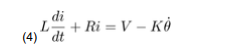
Rotational speed is considered the output, and the armature voltage is considered the input.
State Variables:
In state-space form, the governing equations above can be expressed by choosing the rotational speed and electric current as the state variables. Again, the armature voltage is treated as the input and the rotational speed is chosen as the output
Please complete the questions below and insert your answers into the relevant sections below.
• Develop the state and output equations for the system (there is only one output – the
rotational speed)
• Model the system in MATLAB.
• Examine the response of rotational speed to a step input force.
• Investigate a range of values for k – how does this affect the system?
• Complete the template below to report your work. Upload to the Moodle Page by 09th
March 23:59. This assignment will contribute 15% towards the module GPA.
Get Solution of this Assessment. Hire Experts to solve this assignment for you Before Deadline.
DC Motor System Assignment Template
1. Show how you developed the state and output equations for the system. Use the
‘equation editor’ in Word to present your equations. No handwritten equations.
Please explain how you developed your equations and then generated your state space
model.
(20%)
2. Present and briefly discuss the response of the system to a step input force.
(10%)
3. Show how the step response is affected by changing the value k, – what value do you start
to see oscillations in the response?
Show within MATLAB how your pole locations have changed from your initial response to a
response with oscillations. Explain by referring to the different poles you obtained and how
your new poles relate to your response.
Please use 3-5 different values and explain how it has affected your system and why.
(50%)
Stuck in Completing this Assignment and feeling stressed ? Take our Private Writing Services
4. Paste all your detailed MATLAB code here with adequate comments.
Also, include code on how you obtained a transfer function of the system within MATLAB.
Also, include code on how you obtained your poles from your MATLAB code.
Also include where your poles are located as well as where they changed to, by changing
your value of k.
(20%)